
Stepper Configuration Wizard
Machinekit is capable of controlling a wide range of machinery using many different hardware interfaces.
Stepconf is a program that generates configuration files for Machinekit for a specific class of CNC machine: those that are controlled via a 'standard parallel port', and controlled by signals of type 'step & direction'.
Stepconf is installed when you install Machinekit and is in the CNC menu.
Stepconf places a file in the machinekit/config directory to store the choices for each configuration you create. When you change something, you need to pick the file that matches your configuration name. The file extension is .stepconf.
The Stepconf Wizard works best with at least 800 x 600 screen resolution.
|
Note
|
Before starting stepconf it is advisable to first run one of the simulated configs, eg. axis_mm. This will ensure your system is working properly and will create a machinekit folder in your home dir if it does not already exist. This is required for stepconf. |
Step by Step Instructions
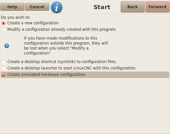
Start Page
-
'Create New' - Creates a fresh configuration.
-
'Modify' - Modify an existing configuration. After selecting this a file picker pops up so you can select the .stepconf file for modification. If you made any modifications to the main .hal or the .ini file these will be lost. Modifications to custom.hal and custom_postgui.hal will not be changed by the Stepconf Wizard. Stepconf will highlight the lastconf that was built.
These next options wiil be recorded in a preference file for the next run of Stepconf.
-
'Create Desktop Shortcut' - This will place a link on your desktop to the files.
-
'Create Desktop Launcher' - This will place a launcher on your desktop to start your application.
-
'Create Simulated Hardware' - This allows you to build a config for testing, even if you don’t have the actual hardware.
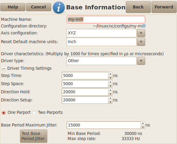
Basic Information
-
'Machine Name' - Choose a name for your machine. Use only uppercase letters, lowercase letters, digits, - and _.
-
'Axis Configuration' - Choose XYZ (Mill), XYZA (4-axis mill) or XZ (Lathe).
-
'Machine Units' - Choose Inch or mm. All subsequent entries will be in the chosen units. Changing this also changes the default values in the Axes section. If you change this after selecting values in any of the axes sections, they will be over-written by the default values of the selected units.
-
'Driver Type' - If you have one of the stepper drivers listed in the pull down box, choose it. Otherwise, select 'Other' and find the timing values in your driver’s data sheet and enter them as 'nano seconds' in the 'Driver Timing Settings'. If the data sheet gives a value in microseconds, multiply by 1000. For example, enter 4.5us as 4500ns.
A list of some popular drives, along with their timing values, is at Stepper Drive Timing.
Additional signal conditioning or isolation such as optocouplers and RC filters on break out boards can impose timing constraints of their own, in addition to those of the driver. You may find it necessary to add some time to the drive requirements to allow for this.
The Machinekit Configuration Selector has configs for Sherline already configured.
-
'Step Time' - How long the step pulse is 'on' in nano seconds. If your not sure about this setting a value of 10,000 will work with most drives.
-
'Step Space' - Minimum time between step pulses in nano seconds. If your not sure about this setting a value of 10,000 will work with most drives.
-
'Direction Hold' - How long the direction pin is held after a change of direction in nanoseconds. If your not sure about this setting a value of 200,000 will work with most drives.
-
'Direction Setup' - How long before a direction change after the last step pulse in nanoseconds. If your not sure about this setting a value of 200,000 will work with most drives.
-
'One / Two Parport' - Select how many parallel port are to be configured.
-
'Base Period Maximum Jitter' - Enter the result of the Latency Test here. To run a latency test press the 'Test Base Period Jitter' button. See the Latency Test section for more details.
-
'Max Step Rate' -Stepconf automatically calculates the Max Step Rate based on the driver characteristics entered and the latency test result.
-
'Min Base Period' - Stepconf automatically determines the Min Base Period based on the driver characteristics entered and latency test result.
The important numbers are the 'max jitter'. In the example above 9075 nanoseconds, or 9.075 microseconds, is the highest jitter. Record this number, and enter it in the Base Period Maximum Jitter box.
If your Max Jitter number is less than about 15-20 microseconds (15000-20000 nanoseconds), the computer should give very nice results with software stepping. If the max latency is more like 30-50 microseconds, you can still get good results, but your maximum step rate might be a little disappointing, especially if you use microstepping or have very fine pitch leadscrews. If the numbers are 100 us or more (100,000 nanoseconds), then the PC is not a good candidate for software stepping. Numbers over 1 millisecond (1,000,000 nanoseconds) mean the PC is not a good candidate for Machinekit, regardless of whether you use software stepping or not.
Parallel Port Setup
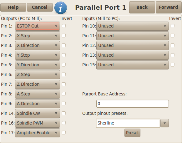
You may specify the address as a hexidecimal (often 0x378) or as linux’s default port number (probably 0)
For each pin, choose the signal which matches your parallel port pinout. Turn on the 'invert' check box if the signal is inverted (0V for true/active, 5V for false/inactive).
-
'Output pinout presets' - Automatically set pins 2 through 9 according to the Sherline standard (Direction on pins 2, 4, 6, 8) or the Xylotex standard (Direction on pins 3, 5, 7, 9).
-
'Inputs and Outputs' - If the input or output is not used set the option to 'Unused'.
-
'External E Stop' - This can be selected from an input pin drop down box. A typical E Stop chain uses all normally closed contacts.
-
'Homing & Limit Switches' - These can be selected from an input pin drop down box for most configurations.
-
'Charge Pump' - If your driver board requires a charge pump signal select Charge Pump from the drop down list for the output pin you wish to connect to your charge pump input. The charge pump output is connected to the base thread by Stepconf. The charge pump output will be about 1/2 of the maximum step rate shown on the Basic Machine Configuration page.
Parallel Port 2 Setup
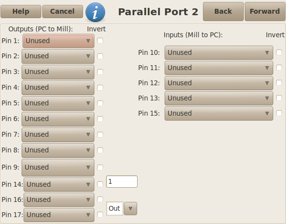
The second Parallel port (if selected) can be configured and It’s pins
assigned on this page.
No step and direction signals can be selected.
You may select in or out to maximizes the number of input/output pins that
are available.
You may specify the address as a hexidecimal (often 0x278) or as linux’s default
port number (probably 1).
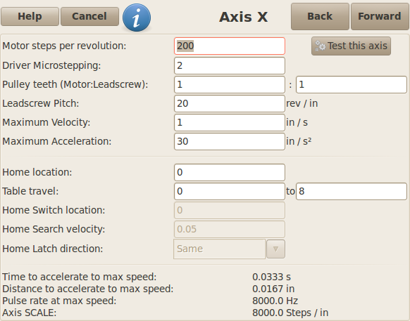
Axis Configuration
-
'Motor Steps Per Revolution' - The number of full steps per motor revolution. If you know how many degrees per step the motor is (e.g., 1.8 degree), then divide 360 by the degrees per step to find the number of steps per motor revolution.
-
'Driver Microstepping' - The amount of microstepping performed by the driver. Enter '2' for half-stepping.
-
'Pulley Ratio' - If your machine has pulleys between the motor and leadscrew, enter the ratio here. If not, enter '1:1'.
-
'Leadscrew Pitch' - Enter the pitch of the leadscrew here. If you chose 'Inch' units, enter the number of threads per inch If you chose 'mm' units, enter the number of millimeters per revolution (e.g., enter 2 for 2mm/rev). If the machine travels in the wrong direction, enter a negative number here instead of a positive number, or invert the direction pin for the axis.
-
'Maximum Velocity' -Enter the maximum velocity for the axis in units per second.
-
'Maximum Acceleration' - The correct values for these items can only be determined through experimentation. See Finding Maximum Velocity to set the speed and Finding Maximum Acceleration to set the acceleration.
-
'Home Location' - The position the machine moves to after completing the homing procedure for this axis. For machines without home switches, this is the location the operator manually moves the machine to before pressing the Home button. If you combine the home and limit switches you must move off of the switch to the home position or you will get a joint limit error.
-
'Table Travel' - The range of travel for that axis based on the machine origin. The home location must be inside the 'Table Travel' and not equal to one of the Table Travel values.
-
'Home Switch Location' - The location at which the home switch trips or releases reletive to the machine origin. This item and the two below only appear when Home Switches were chosen in the Parallel Port Pinout. If you combine home and limit switches the home switch location can not be the same as the home position or you will get a joint limit error.
-
'Home Search Velocity' - The velocity to use when searching for the home switch. If the switch is near the end of travel, this velocity must be chosen so that the axis can decelerate to a stop before hitting the end of travel. If the switch is only closed for a short range of travel (instead of being closed from its trip point to one end of travel), this velocity must be chosen so that the axis can decelerate to a stop before the switch opens again, and homing must always be started from the same side of the switch. If the machine moves the wrong direction at the beginning of the homing procedure, negate the value of 'Home Search Velocity'.
-
'Home Latch Direction' - Choose 'Same' to have the axis back off the switch, then approach it again at a very low speed. The second time the switch closes, the home position is set. Choose 'Opposite' to have the axis back off the switch and when the switch opens, the home position is set.
-
'Time to accelerate to max speed' - Time to reach maximum speed calculated from 'Max Acceleration' and 'Max Velocity'.
-
'Distance to accelerate to max speed' - Distance to reach maximum speed from a standstill.
-
'Pulse rate at max speed' - Information computed based on the values entered above. The greatest 'Pulse rate at max speed' determines the 'BASE_PERIOD'. Values above 20000Hz may lead to slow response time or even lockups (the fastest usable pulse rate varies from computer to computer)
-
'Axis SCALE' - The number that will be used in the ini file [SCALE] setting. This is how many steps per user unit.
-
'Test this axis' - This will open a window to allow testing for each axis. This can be used after filling out all the information for this axis.
Test This Axis
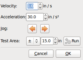
Test this axis is a basic tester that only outputs step and direction signals to try different values for acceleration and velocity.
|
Important
|
In order to use test this axis you have to manually enable the axis if this is required. If your driver has a charge pump you will have to bypass it. Test this axis does not react to limit switch inputs. Use with caution. |
Finding Maximum Velocity
Begin with a low Acceleration (for example, 2 inches/s^2^ or 50 mm/s^2^) and the velocity you hope to attain. Using the buttons provided, jog the axis to near the center of travel. Take care because with a low acceleration value, it can take a surprising distance for the axis to decelerate to a stop.
After gaging the amount of travel available, enter a safe distance in Test Area, keeping in mind that after a stall the motor may next start to move in an unexpected direction. Then click Run. The machine will begin to move back and forth along this axis. In this test, it is important that the combination of Acceleration and Test Area allow the machine to reach the selected Velocity and 'cruise' for at least a short distance — the more distance, the better this test is. The formula d = 0.5 * v * v/a gives the minimum distance required to reach the specified velocity with the given acceleration. If it is convenient and safe to do so, push the table against the direction of motion to simulate cutting forces. If the machine stalls, reduce the speed and start the test again.
If the machine did not obviously stall, click the 'Run' button off. The axis now returns to the position where it started. If the position is incorrect, then the axis stalled or lost steps during the test. Reduce Velocity and start the test again.
If the machine doesn’t move, stalls, or loses steps, no matter how low you turn Velocity, verify the following:
-
Correct step waveform timings
-
Correct pinout, including 'Invert' on step pins
-
Correct, well-shielded cabling
-
Physical problems with the motor, motor coupling, leadscrew, etc.
Once you have found a speed at which the axis does not stall or lose steps during this testing procedure, reduce it by 10% and use that as the axis 'Maximum Velocity'.
Finding Maximum Acceleration
With the Maximum Velocity you found in the previous step, enter the acceleration value to test. Using the same procedure as above, adjust the Acceleration value up or down as necessary. In this test, it is important that the combination of Acceleration and Test Area allow the machine to reach the selected Velocity. Once you have found a value at which the axis does not stall or lose steps during this testing procedure, reduce it by 10% and use that as the axis Maximum Acceleration.
Spindle Configuration
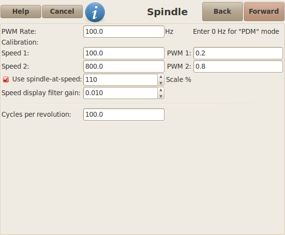
This page only appears when 'Spindle PWM' is chosen in the 'Parallel Port Pinout' page for one of the outputs.
Spindle Speed Control
If 'Spindle PWM' appears on the pinout, the following information should be entered:
-
'PWM Rate' - The 'carrier frequency' of the PWM signal to the spindle. Enter '0' for PDM mode, which is useful for generating an analog control voltage. Refer to the documentation for your spindle controller for the appropriate value.
-
'Speed 1 and 2, PWM 1 and 2' - The generated configuration file uses a simple linear relationship to determine the PWM value for a given RPM value. If the values are not known, they can be determined. For more information see Determining Spindle Calibration.
Spindle-synchronized motion
When the appropriate signals from a spindle encoder are connected to Machinekit via HAL, Machinekit supports lathe threading. These signals are:
-
'Spindle Index' - Is a pulse that occurs once per revolution of the spindle.
-
'Spindle Phase A' - This is a pulse that occurs in multiple equally-spaced locations as the spindle turns.
-
'Spindle Phase B (optional)' - This is a second pulse that occurs, but with an offset from Spindle Phase A. The advantages to using both A and B are direction sensing, increased noise immunity, and increased resolution.
If 'Spindle Phase A' and 'Spindle Index' appear on the pinout, the following information should be entered:
-
'Use Spindle-At-Speed' - With encoder feedback one can choose to have machinekit wait for the spindle to reach the commanded speed before feed moves. Select this option and set the 'close enough' scale.
-
'Speed Display Filter Gain' - Setting for adjusting the stability of the visual spindle speed display.
-
'Cycles per revolution' - The number of cycles of the 'Spindle A' signal during one revolution of the spindle. This option is only enabled when an input has been set to 'Spindle Phase A'
-
'Maximum speed in thread' - The maximum spindle speed used in threading. For a high spindle RPM or a spindle encoder with high resolution, a low value of 'BASE_PERIOD' is required.
Determining Spindle Calibration
Enter the following values in the Spindle Configuration page:
Speed 1: |
0 |
PWM 1: |
0 |
Speed 2: |
1000 |
PWM 2: |
1 |
Finish the remaining steps of the configuration process, then launch Machinekit with your configuration. Turn the machine on and select the MDI tab. Start the spindle turning by entering: 'M3 S100'. Change the spindle speed by entering a different S-number: 'S800'. Valid numbers (at this point) range from 1 to 1000.
For two different S-numbers, measure the actual spindle speed in RPM. Record the S-numbers and actual spindle speeds. Run Stepconf again. For 'Speed' enter the measured speed, and for 'PWM' enter the S-number divided by 1000.
Because most spindle drivers are somewhat nonlinear in their response curves, it is best to:
-
Make sure the two calibration speeds are not too close together in RPM
-
Make sure the two calibration speeds are in the range of speeds you will typically use while milling
For instance, if your spindle will go from 0 RPM to 8000 RPM, but you generally use speeds from 400 RPM (10%) to 4000 RPM (100%), then find the PWM values that give 1600 RPM (40%) and 2800 RPM (70%).
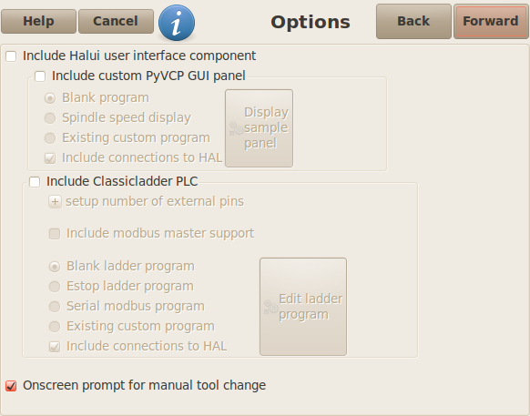
Options
-
'Include Halui' - This will add the Halui user interface component. See the Integrator Manual for more information on Halui.
-
'Include pyVCP' - This option adds the pyVCP panel base file or a sample file to work on. See the Integrator Manual for more information on pyVCP.
-
'Include ClassicLadder PLC' - This option will add the ClassicLadder PLC (Programmable Logic Controller). See the Integrator Manual for more information on ClassicLadder.
-
'Onscreen Prompt For Tool Change' - If this box is checked, Machinekit will pause and prompt you to change the tool when 'M6' is encountered. This feature is usually only useful if you have presettable tools.
Machine Configuration Complete
Click 'Apply' to write the configuration files. Later, you can re-run this program and tweak the settings you entered before.
Axis Travel, Home Location, and Home Switch Location
For each axis, there is a limited range of travel. The physical end of travel is called the 'hard stop'.
Before the 'hard stop' there is a 'limit switch'. If the limit switch is encountered during normal operation, Machinekit shuts down the motor amplifier. The distance between the 'hard stop' and 'limit switch' must be long enough to allow an unpowered motor to coast to a stop.
Before the 'limit switch' there is a 'soft limit'. This is a limit enforced in software after homing. If a MDI command or g code program would pass the soft limit, it is not executed. If a jog would pass the soft limit, it is terminated at the soft limit.
The 'home switch' can be placed anywhere within the travel (between hard stops). As long as external hardware does not deactivate the motor amplifiers when the limit switch is reached, one of the limit switches can be used as a home switch.
The 'zero position' is the location on the axis that is 0 in the machine coordinate system. Usually the 'zero position' will be within the 'soft limits'. On lathes, constant surface speed mode requires that machine 'X=0' correspond to the center of spindle rotation when no tool offset is in effect.
The 'home position' is the location within travel that the axis will be moved to at the end of the homing sequence. This value must be within the 'soft limits'. In particular, the 'home position' should never be exactly equal to a 'soft limit'.
Operating without Limit Switches
A machine can be operated without limit switches. In this case, only the soft limits stop the machine from reaching the hard stop. Soft limits only operate after the machine has been homed.
Operating without Home Switches
A machine can be operated without home switches. If the machine has limit switches, but no home switches, it is best to use a limit switch as the home switch (e.g., choose 'Minimum Limit + Home X' in the pinout). If the machine has no switches at all, or the limit switches cannot be used as home switches for another reason, then the machine must be homed 'by eye' or by using match marks. Homing by eye is not as repeatable as homing to switches, but it still allows the soft limits to be useful.
Home and Limit Switch wiring options
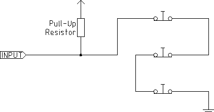
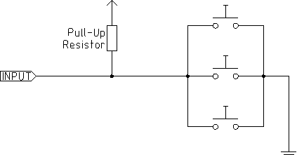
The ideal wiring for external switches would be one input per switch. However, the PC parallel port only offers a total of 5 inputs, while there are as many as 9 switches on a 3-axis machine. Instead, multiple switches are wired together in various ways so that a smaller number of inputs are required.
The figures below show the general idea of wiring multiple switches to a single input pin. In each case, when one switch is actuated, the value seen on INPUT goes from logic HIGH to LOW. However, Machinekit expects a TRUE value when a switch is closed, so the corresponding 'Invert' box must be checked on the pinout configuration page. The pull up resistor show in the diagrams pulls the input high until the connection to ground is made and then the input goes low. Otherwise the input might float between on and off when the circuit is open. Typically for a parallel port you might use 47k.
The following combinations of switches are permitted in Stepconf:
-
Combine home switches for all axes
-
Combine limit switches for all axes
-
Combine both limit switches for one axis
-
Combine both limit switches and the home switch for one axis
-
Combine one limit switch and the home switch for one axis