
INI Configuration
The INI File Components
A typical INI file follows a rather simple layout that includes;
-
comments
-
sections
-
variables
Each of these elements is separated on single lines. Each end of line or newline character creates a new element.
Comments
A comment line is started with a ; or a # mark. When the ini reader sees either of these marks at the start a line, the rest of the line is ignored by the software. Comments can be used to describe what an INI element will do.
; This is my mill configuration file.
# I set it up on January 12, 2012
Comments can also be used to 'turn off' a variable. This makes it easier to pick between different variables.
DISPLAY = axis
# DISPLAY = touchy
In this list, the DISPLAY variable will be set to axis because the other one is commented out. If someone carelessly edits a list like this and leaves two of the lines uncommented, the first one encountered will be used.
Note that inside a variable, the "#" and ";" characters do not denote comments:
INCORRECT = value     # and a comment

# Correct Comment
CORRECT = value
Sections
Related parts of an ini file are separated into sections. A section name is enclosed in brackets like this '[THIS_SECTION]' The order of sections is unimportant. Sections begin at the section name and end at the next section name.
The following sections are used by Machinekit:
-
'[EMC]' general information
-
'[DISPLAY]' settings related to the graphical user interface
-
'[FILTER]' settings input filter programs
-
'[RS274NGC]' settings used by the g-code interpreter
-
'[EMCMOT]' settings used by the real time motion controller
-
'[TASK]' settings used by the task controller
-
'[HAL]' specifies .hal files
-
'[HALUI]' MDI commands used by HALUI
-
'[TRAJ]' additional settings used by the real time motion controller
-
'[AXIS_n]' individual axis variables
-
'[EMCIO]' settings used by the I/O Controller
Variables
A variable line is made up of a variable name, an equals sign (=), and a value. Everything from the first non-white space character after the = up to the end of the line is passed as the value, so you can embed spaces in string symbols if you want to or need to. A variable name is often called a keyword.
The following sections detail each section of the configuration file, using sample values for the configuration lines.
Variables that are used by Machinekit must always use the section names and variable names as shown. In the following example the variable 'MACHINE' is assigned the value 'My Machine'.
MACHINE = My MachineCustom Sections and Variables
Most sample configurations use custom sections and variables to put all of the settings into one location for convenience.
To use a custom section variable in your HAL file add the section and variable to the INI file.
[OFFSETS]
OFFSET_1 = 0.1234
To add a custom variable to a Machinekit section simply include the variable in that section.
[AXIS_0]
TYPE = LINEAR
...
SCALE = 16000
To use the custom variables in your HAL file put the section and variable name in place of the value.
setp offset.1.offset [OFFSETS]OFFSET_1
setp stepgen.0.position-scale [AXIS_0]SCALE|
Note
|
The value stored in the variable must match the type specified by the component pin. |
Include Files
An INI file may include the contents of another file by using a #INCLUDE directive.
#INCLUDE filenameThe filename can be specified as:
-
a file in the same directory as the INI file
-
a file located relative to the working directory
-
an absolute file name (starts with a /)
-
a user-home-relative file name (starts with a ~)
Multiple #INCLUDE directives are supported.
#INCLUDE axis_0.inc
#INCLUDE ../parallel/axis_1.inc
#INCLUDE below/axis_2.inc
#INCLUDE /home/myusername/myincludes/display.inc
#INCLUDE ~/machinekit/myincludes/rs274ngc.inc
The #INCLUDE directives are supported for one level of expansion only — an included file may not include additional files. The recommended file extension is .inc. Do not use a file extension of .ini for included files.
INI File Sections
[EMC] Section
-
'VERSION = $Revision: 1.3 $' - The version number for the INI file. The value shown here looks odd because it is automatically updated when using the Revision Control System. It’s a good idea to change this number each time you revise your file. If you want to edit this manually just change the number and leave the other tags alone.
-
'MACHINE = My Controller' - This is the name of the controller, which is printed out at the top of most graphical interfaces. You can put whatever you want here as long as you make it a single line long.
-
'DEBUG = 0' - Debug level 0 means no messages will be printed when Machinekit is run from a terminal. Debug flags are usually only useful to developers. See src/emc/nml_intf/debugflags.h for other settings.
[DISPLAY] Section
Different user interface programs use different options, and not every option is supported by every user interface. The main two interfaces for Machinekit are AXIS and Touchy. Axis is an interface for use with normal computer and monitor, Touchy is for use with touch screens. Descriptions of the interfaces are in the Interfaces section of the User Manual.
-
'DISPLAY = axis' - The name of the user interface to use. Valid options may include: axis, touchy, keystick, mini, tkmachinekit, xemc,
-
'POSITION_OFFSET = RELATIVE' - The coordinate system (RELATIVE or MACHINE) to show when the user interface starts. The RELATIVE coordinate system reflects the G92 and G5x coordinate offsets currently in effect.
-
'POSITION_FEEDBACK = ACTUAL' - The coordinate value (COMMANDED or ACTUAL) to show when the user interface starts. The COMMANDED position is the ideal position requested by Machinekit. The ACTUAL position is the feedback position of the motors.
-
'MAX_FEED_OVERRIDE = 1.2' - The maximum feed override the user may select. 1.2 means 120% of the programmed feed rate.
-
'MIN_SPINDLE_OVERRIDE = 0.5' - The minimum spindle override the user may select. 0.5 means 50% of the programmed spindle speed. (This is useful as it’s dangerous to run a program with a too low spindle speed).
-
'MAX_SPINDLE_OVERRIDE = 1.0' - The maximum spindle override the user may select. 1.0 means 100% of the programmed spindle speed.
-
'PROGRAM_PREFIX = ~/machinekit/nc_files' - The default location for g-code files and the location for user-defined M-codes. This location is searched for the file name before the subroutine path and user M path if specified in the [RS274NGC] section.
-
'INTRO_GRAPHIC = emc2.gif' - The image shown on the splash screen.
-
'INTRO_TIME = 5' - The maximum time to show the splash screen, in seconds.
-
'CYCLE_TIME = 0.05' - Cycle time in seconds that display will sleep between polls.
|
Note
|
The following [DISPLAY] items are for the AXIS interface only. |
-
'DEFAULT_LINEAR_VELOCITY = .25' - The default velocity for linear jogs, in , machine units per second.
-
'MIN_VELOCITY = .01' - The approximate lowest value the jog slider.
-
'MAX_LINEAR_VELOCITY = 1.0' - The maximum velocity for linear jogs, in machine units per second.
-
'MIN_LINEAR_VELOCITY = .01' - The approximate lowest value the jog slider.
-
'DEFAULT_ANGULAR_VELOCITY = .25' - The default velocity for angular jogs, in machine units per second.
-
'MIN_ANGULAR_VELOCITY = .01' - The approximate lowest value the angular jog slider.
-
'MAX_ANGULAR_VELOCITY = 1.0' - The maximum velocity for angular jogs, in machine units per second.
-
'INCREMENTS = 1 mm, .5 in, …' - Defines the increments available for incremental jogs. The INCREMENTS can be used to override the default. The values can be decimal numbers (e.g., 0.1000) or fractional numbers (e.g., 1/16), optionally followed by a unit (cm, mm, um, inch, in or mil). If a unit is not specified the machine unit is assumed. Metric and imperial distances may be mixed: INCREMENTS = 1 inch, 1 mil, 1 cm, 1 mm, 1 um is a valid entry.
-
'GRIDS = 10 mm, 1 in, …' - Defines the preset values for grid lines. The value is interpreted the same way as 'INCREMENTS'.
-
'OPEN_FILE = /full/path/to/file.ngc' - The file to show in the preview plot when AXIS starts. Use a blank string "" and no file will be loaded at start up.
-
'EDITOR = gedit' - The editor to use when selecting File > Edit to edit the G code from the AXIS menu. This must be configured for this menu item to work. Another valid entry is gnome-terminal -e vim.
-
'TOOL_EDITOR = tooledit' - The editor to use when editing the tool table (for example by selecting "File > Edit tool table…" in Axis). Other valid entries are "gedit", "gnome-terminal -e vim", and "gvim".
-
'PYVCP = /filename.xml' - The PyVCP panel description file. See the PyVCP section for more information.
-
'LATHE = 1' - This displays in lathe mode with a top view and with Radius and Diameter on the DRO.
-
'GEOMETRY = XYZABCUVW' - Controls the preview and backplot of rotary motion. This item consists of a sequence of axis letters, optionally preceded by a "-" sign. Only axes defined in '[TRAJ]AXES' should be used. This sequence specifies the order in which the effect of each axis is applied, with a "-" inverting the sense of the rotation. The proper GEOMETRY string depends on the machine configuration and the kinematics used to control it. The example string GEOMETRY=XYZBCUVW is for a 5-axis machine where kinematics causes UVW to move in the coordinate system of the tool and XYZ to move in the coordinate system of the material. The order of the letters is important, because it expresses the order in which the different transformations are applied. For example rotating around C then B is different than rotating around B then C. Geometry has no effect without a rotary axis.
-
'ARCDIVISION = 64' - Set the quality of preview of arcs. Arcs are previewed by dividing them into a number of straight lines; a semicircle is divided into ARCDIVISION parts. Larger values give a more accurate preview, but take longer to load and result in a more sluggish display. Smaller values give a less accurate preview, but take less time to load and may result in a faster display. The default value of 64 means a circle of up to 3 inches will be displayed to within 1 mil (.03%).[1]
-
'MDI_HISTORY_FILE =' - The name of a local MDI history file. If this is not specified Axis will save the MDI history in .axis_mdi_history in the user’s home directory. This is useful if you have multiple configurations on one computer.
|
Note
|
The following [DISPLAY] item is used by the TKMachinekit interface only. |
-
'HELP_FILE = tklinucnc.txt' - Path to help file.
[FILTER] Section
AXIS has the ability to send loaded files through a filter program. This filter can do any desired task: Something as simple as making sure the file ends with M2, or something as complicated as detecting whether the input is a depth image, and generating g-code to mill the shape it defines. The [FILTER] section of the ini file controls how filters work. First, for each type of file, write a PROGRAM_EXTENSION line. Then, specify the program to execute for each type of file. This program is given the name of the input file as its first argument, and must write RS274NGC code to standard output. This output is what will be displayed in the text area, previewed in the display area, and executed by Machinekit when Run.
-
'PROGRAM_EXTENSION = .extension Description'
If your post processor outputs files in all caps you might want to add the following line:
-
'PROGRAM_EXTENSION = .NGC XYZ Post Processor'
The following lines add support for the image-to-gcode converter included with Machinekit:
-
'PROGRAM_EXTENSION = .png,.gif,.jpg Greyscale Depth Image'
-
'png = image-to-gcode'
-
'gif = image-to-gcode'
-
'jpg = image-to-gcode'
-
It is also possible to specify an interpreter:
-
'PROGRAM_EXTENSION = .py Python Script'
-
'py = python'
-
In this way, any Python script can be opened, and its output is treated as g-code. One such example script is available at nc_files/holecircle.py. This script creates g-code for drilling a series of holes along the circumference of a circle. Many more g-code generators are on the Machinekit Wiki site http://wiki.linuxcnc.org/.
If the environment variable AXIS_PROGRESS_BAR is set, then lines written to stderr of the form
-
'FILTER_PROGRESS=%d'
sets the AXIS progress bar to the given percentage. This feature should be used by any filter that runs for a long time.
Python filters should use the print function to output the result to Axis.
This example program filters a file and adds a W axis to match the Z axis. It depends on there being a space between each axis word to work.
#! /usr/bin/env python

import sys

def main(argv):

  openfile = open(argv[0], 'r')
  file_in = openfile.readlines()
  openfile.close()

  file_out = []
  for line in file_in:
    # print line
    if line.find('Z') != -1:
      words = line.rstrip('\n')
      words = words.split(' ')
      newword = ''
      for i in words:
        if i[0] == 'Z':
          newword = 'W'+ i[1:]
      if len(newword) > 0:
        words.append(newword)
        newline = ' '.join(words)
        file_out.append(newline)
    else:
      file_out.append(line)
  for item in file_out:
    print "%s" % item

if __name__ == "__main__":
   main(sys.argv[1:])
[USER_COMMANDS] Section
-
'USER0 = #setp iocontrol.0.lube_level 1'
-
'USER1 = G0 X0 Y0 Z0'
-
'USER2 = G0 X5 Y5 Z5'
-
'USER3 = G0 X10 Y10 Z10'
-
'USER4 = G0 X15 Y15 Z15'
-
'USER5 = G0 X20 Y20 Z20'
-
'USER6 = G0 X25 Y25'
-
'USER7 = G0 X30 Y30'
-
'USER8 = $firefox "www.machinekit.io"'
-
'USER9 = $gedit'
Ten user commands can be specified in the ini file.
# precedes a halcmd
This will be sent and the return waited for before continuing
$ precedes a system command
This will be spawned to a new process and return immediately
No prefix before a gcode instruction
The commands are accessed from the extra dropdown User menu
(see below re key binding)
-
'NUMKEYS = YES'
To bind the user keys to the numeric 0-9 keys, set NUMKEYS = YES
Use this carefully, the main reason for its inclusion
is to allow HID type pendant to operate commands from keystrokes
If using a keyboard, probably best set to NO and just use Alt U + n (0-9).
-
'DISABLE_PREVIEW = YES'
Loading big files can seriously slow down or even crash Axis if the preview is enabled,
because it consumes huge amounts of memory.
This option turns the preview off.  The live plot will still be drawn.
-
'LOAD_LASTFILE = YES'
Unless Machinekit is launched with a file in the command line,
or there is a file specified to be opened in the ini file
or in the environment variable,
the file that was open when machinekit was last closed, will be re-opened.
Use with caution if you use very large and frequently changing files,
as this could slow down launch considerably waiting for the last file to load.
[RS274NGC] Section
-
'PARAMETER_FILE = myfile.var' - The file located in the same directory as the ini file which contains the parameters used by the interpreter (saved between runs).
-
'ORIENT_OFFSET = 0' - A float value added to the R word parameter of an M19 Orient Spindle operation. Used to define an arbitrary zero position regardless of encoder mount orientation.
-
'RS274NGC_STARTUP_CODE = G01 G17 G20 G40 G49 G64 P0.001 G80 G90 G92 G94 G97 G98' - A string of NC codes that the interpreter is initialized with. This is not a substitute for specifying modal g-codes at the top of each ngc file, because the modal codes of machines differ, and may be changed by g-code interpreted earlier in the session.
-
'SUBROUTINE_PATH = ncsubroutines:/tmp/testsubs:lathesubs:millsubs' - Specifies a colon (:) separated list of up to 10 directories to be searched when single-file subroutines are specified in gcode. These directories are searched after searching [DISPLAY]PROGRAM_PREFIX (if it is specified) and before searching [WIZARD]WIZARD_ROOT (if specified). The paths are searched in the order that they are listed. The first matching subroutine file found in the search is used. Directories are specified relative to the current directory for the ini file or as absolute paths. The list must contain no intervening whitespace.
-
'USER_M_PATH = myfuncs:/tmp/mcodes:experimentalmcodes' - Specifies a list of colon (:) separated directories for user defined functions. Directories are specified relative to the current directory for the ini file or as absolute paths. The list must contain no intervening whitespace.
A search is made for each possible user defined function, typically (M100-M199). The search order is:
-
[DISPLAY]PROGRAM_PREFIX (if specified)
-
If [DISPLAY]PROGRAM_PREFIX is not specified, search the default location: nc_files
-
Then search each directory in the list [RS274NGC]USER_M_PATH
The first executable M1xx found in the search is used for each M1xx.
-
-
'USER_DEFINED_FUNCTION_MAX_DIRS=5'. The maximum number of directories defined at compile time.
-
'TOLERANCE_INCH = 0.0028' - Specifies the arc tolerance in imperial units to be used by the interpreter. If a valid figure, currently between 0.0028" and 0.00004", this figure will be used by the interpreter, instead of the default of 0.0028".
-
'TOLERANCE_MM = 0.0282' - Specifies the arc tolerance in metric units to be used by the interpreter. If a valid figure, currently between 0.0282mm and 0.001mm, this figure will be used by the interpreter, instead of the default of 0.0282mm.
TOLERANCE fields are primarily of use when using code produced by CAM. The default figures should now cater for CAM code which has rounded up values for I J K figures, which previously would have produced errors. If you require a higher degree of accuracy in arc tolerance calculation, this can be specified down to 1 micron (0.001mm) or the imperial equivalent.
Most users can ignore these fields and use the defaults.
+
|
Note
|
[WIZARD]WIZARD_ROOT is a valid search path but the Wizard has not been fully implemented and the results of using it are unpredictable. |
[EMCMOT] Section
This section is a custom section and is not used by Machinekit directly. Most configurations use values from this section to load the motion controller. For more information on the motion controller see the Motion Section.
-
'EMCMOT = motmod' - the motion controller name is typically used here.
-
'BASE_PERIOD = 50000' - the 'Base' task period in nanoseconds.
-
'SERVO_PERIOD = 1000000' - This is the "Servo" task period in nanoseconds.
-
'TRAJ_PERIOD = 100000' - This is the 'Trajectory Planner' task period in nanoseconds.
[TASK] Section
-
'TASK = milltask' - Specifies the name of the 'task' executable. The 'task' executable does various things, such as communicate with the UIs over NML, communicate with the realtime motion planner over non-HAL shared memory, and interpret gcode. Currently there is only one task executable that makes sense for 99.9% of users, milltask.
-
'CYCLE_TIME = 0.010' - The period, in seconds, at which TASK will run. This parameter affects the polling interval when waiting for motion to complete, when executing a pause instruction, and when accepting a command from a user interface. There is usually no need to change this number.
[HAL] section
-
'TWOPASS=ON' - Use two pass processing for loading HAL comps. With TWOPASS processing, all [HAL]HALFILES are first read and multiple appearances of loadrt directives for each moduleb are accumulated. No hal commands are executed in this initial pass.
-
'HALFILE = example.hal' - Execute the file 'example.hal' at start up. If 'HALFILE' is specified multiple times, the files are executed in the order they appear in the ini file. Almost all configurations will have at least one 'HALFILE', and stepper systems typically have two such files, one which specifies the generic stepper configuration ('core_stepper.hal') and one which specifies the machine pin out ('xxx_pinout.hal')
-
'HALCMD = command' - Execute 'command' as a single HAL command. If 'HALCMD' is specified multiple times, the commands are executed in the order they appear in the ini file. 'HALCMD' lines are executed after all 'HALFILE' lines.
-
'SHUTDOWN = shutdown.hal' - Execute the file 'shutdown.hal' when Machinekit is exiting. Depending on the hardware drivers used, this may make it possible to set outputs to defined values when Machinekit is exited normally. However, because there is no guarantee this file will be executed (for instance, in the case of a computer crash) it is not a replacement for a proper physical e-stop chain or other protections against software failure.
-
'POSTGUI_HALFILE = example2.hal' - (Only with the TOUCHY and AXIS GUI) Execute 'example2.hal' after the GUI has created its HAL pins. See section pyVCP with Axis Section for more information.
-
'HALUI = halui' - adds the HAL user interface pins. For more information see the HAL User Interface chapter.
[HALUI] section
-
'MDI_COMMAND = G53 G0 X0 Y0 Z0' - An MDI command can be executed by using halui.mdi-command-00. Increment the number for each command listed in the [HALUI] section.
[TRAJ] Section
The [TRAJ] section contains general parameters for the trajectory planning module in 'motion'.
-
'COORDINATES = X Y Z' - The names of the axes being controlled. Only X, Y, Z, A, B, C, U, V, W are valid. Only axes named in 'COORDINATES' are accepted in g-code. This has no effect on the mapping from G-code axis names (X- Y- Z-) to joint numbers—for 'trivial kinematics', X is always joint 0, A is always joint 3, and U is always joint 6, and so on. It is permitted to write an axis name twice (e.g., X Y Y Z for a gantry machine) but this has no effect.
-
'AXES = 3' - One more than the number of the highest joint number in the system. For an XYZ machine, the joints are numbered 0, 1 and 2; in this case AXES should be 3. For an XYUV machine using 'trivial kinematics', the V joint is numbered 7 and therefore AXES should be 8. For a machine with nontrivial kinematics (e.g., scarakins) this will generally be the number of controlled joints.
-
'JOINTS = 3' - (This config variable is used by the Axis GUI only, not by the trajectory planner in the motion controller.) Specifies the number of joints (motors) in the system. For example, an XYZ machine with a single motor for each axis has 3 joints. A gantry machine with one motor on each of two of the axes, and two motors on the third axis, has 4 joints.
-
'HOME = 0 0 0' - Coordinates of the homed position of each axis. Again for a fourth axis you will need 0 0 0 0. This value is only used for machines with nontrivial kinematics. On machines with trivial kinematics this value is ignored.
-
'LINEAR_UNITS = <units>' - Specifies the 'machine units' for linear axes. Possible choices are (in, inch, imperial, metric, mm). This does not affect the linear units in NC code (the G20 and G21 words do this).
-
'ANGULAR_UNITS = <units>' - Specifies the 'machine units' for rotational axes. Possible choices are 'deg', 'degree' (360 per circle), 'rad', 'radian' (2pi per circle), 'grad', or 'gon' (400 per circle). This does not affect the angular units of NC code. In RS274NGC, A-, B- and C- words are always expressed in degrees.
-
'DEFAULT_VELOCITY = 0.0167' - The initial rate for jogs of linear axes, in machine units per second. The value shown in 'Axis' equals machine units per minute.
-
'DEFAULT_ACCELERATION = 2.0' - In machines with nontrivial kinematics, the acceleration used for "teleop" (Cartesian space) jogs, in 'machine units' per second per second.
-
'MAX_VELOCITY = 5.0' - The maximum velocity for any axis or coordinated move, in 'machine units' per second. The value shown equals 300 units per minute.
-
'MAX_ACCELERATION = 20.0' - The maximum acceleration for any axis or coordinated axis move, in 'machine units' per second per second.
-
'POSITION_FILE = position.txt' - If set to a non-empty value, the joint positions are stored between runs in this file. This allows the machine to start with the same coordinates it had on shutdown. This assumes there was no movement of the machine while powered off. If unset, joint positions are not stored and will begin at 0 each time Machinekit is started. This can help on smaller machines without home switches.
-
'NO_FORCE_HOMING = 1' - The default behavior is for Machinekit to force the user to home the machine before any MDI command or a program is run. Normally, only jogging is allowed before homing. Setting NO_FORCE_HOMING = 1 allows the user to make MDI moves and run programs without homing the machine first. Interfaces without homing ability will need to have this option set to 1.
|
Warning
|
Using this will allow the machine to go beyond the soft limits while in operation. It is not generally desirable to allow this. |
[AXIS_<num>] Section
The [AXIS_0], [AXIS_1], etc. sections contains general parameters for the individual components in the axis control module. The axis section names begin numbering at 0, and run through the number of axes specified in the [TRAJ] AXES entry minus 1.
Typically (but not always):
-
AXIS_0 = X
-
AXIS_1 = Y
-
AXIS_2 = Z
-
AXIS_3 = A
-
AXIS_4 = B
-
AXIS_5 = C
-
AXIS_6 = U
-
AXIS_7 = V
-
AXIS_8 = W
-
'TYPE = LINEAR' - The type of axes, either LINEAR or ANGULAR.
-
'WRAPPED_ROTARY = 1' - When this is set to 1 for an ANGULAR axis the axis will move 0-359.999 degrees. Positive Numbers will move the axis in a positive direction and negative numbers will move the axis in the negative direction.
-
'LOCKING_INDEXER = 1' - When this is set to 1 a G0 move for this axis will initiate an unlock with axis.N.unlock pin then wait for the axis.N.is-unlocked pin then move the axis at the rapid rate for that axis. After the move the axis.N.unlock will be false and motion will wait for axis.N.is-unlocked to go false. Moving with other axes is not allowed when moving a locked rotary axis.
-
'UNITS = INCH' - If specified, this setting overrides the related [TRAJ] UNITS setting. (e.g., [TRAJ]LINEAR_UNITS if the TYPE of this axis is LINEAR, [TRAJ]ANGULAR_UNITS if the TYPE of this axis is ANGULAR)
-
'MAX_VELOCITY = 1.2' - Maximum velocity for this axis in machine units per second.
-
'MAX_ACCELERATION = 20.0' - Maximum acceleration for this axis in machine units per second squared.
-
'BACKLASH = 0.0000' - Backlash in machine units. Backlash compensation value can be used to make up for small deficiencies in the hardware used to drive an axis. If backlash is added to an axis and you are using steppers the STEPGEN_MAXACCEL must be increased to 1.5 to 2 times the MAX_ACCELERATION for the axis.
-
'COMP_FILE = file.extension' - A file holding compensation structure for the axis. The file could be named xscrew.comp, for example, for the X axis. File names are case sensitive and can contain letters and/or numbers. The values are triplets per line separated by a space. The first value is nominal (where it should be). The second and third values depend on the setting of COMP_FILE_TYPE. Currently the limit inside Machinekit is for 256 triplets per axis. If COMP_FILE is specified, BACKLASH is ignored. Compensation file values are in machine units.
-
'COMP_FILE_TYPE = 0 or 1' -
-
'If 0:' The second and third values specify the forward position (where the axis is while traveling forward) and the reverse position (where the axis is while traveling reverse), positions which correspond to the nominal position.'
-
'If 1:' The second and third values specify the forward trim (how far from nominal while traveling forward) and the reverse trim (how far from nominal while traveling in reverse), positions which correspond to the nominal position.
Example triplet with COMP_FILE_TYPE = 0: 1.00 1.01 0.99 +
Example triplet with COMP_FILE_TYPE = 1: 1.00 0.01 -0.01
-
-
'MIN_LIMIT = -1000' - The minimum limit (soft limit) for axis motion, in machine units. When this limit is exceeded, the controller aborts axis motion.
-
'MAX_LIMIT = 1000' - The maximum limit (soft limit) for axis motion, in machine units. When this limit is exceeded, the controller aborts axis motion.
-
'MIN_FERROR = 0.010' - This is the value in machine units by which the axis is permitted to deviate from commanded position at very low speeds. If MIN_FERROR is smaller than FERROR, the two produce a ramp of error trip points. You could think of this as a graph where one dimension is speed and the other is permitted following error. As speed increases the amount of following error also increases toward the FERROR value.
-
'FERROR = 1.0' - FERROR is the maximum allowable following error, in machine units. If the difference between commanded and sensed position exceeds this amount, the controller disables servo calculations, sets all the outputs to 0.0, and disables the amplifiers. If MIN_FERROR is present in the .ini file, velocity-proportional following errors are used. Here, the maximum allowable following error is proportional to the speed, with FERROR applying to the rapid rate set by [TRAJ]MAX_VELOCITY, and proportionally smaller following errors for slower speeds. The maximum allowable following error will always be greater than MIN_FERROR. This prevents small following errors for stationary axes from inadvertently aborting motion. Small following errors will always be present due to vibration, etc. The following polarity values determine how inputs are interpreted and how outputs are applied. They can usually be set via trial-and-error since there are only two possibilities. The Machinekit Servo Axis Calibration utility program (in the AXIS interface menu Machine/Calibration and in TkMachinekit it is under Setting/Calibration) can be used to set these and more interactively and verify their results so that the proper values can be put in the INI file with a minimum of trouble.
Homing
These parameters are Homing related, for a better explanation read the Homing Configuration Chapter.
-
'HOME = 0.0' - The position that the joint will go to upon completion of the homing sequence.
-
'HOME_OFFSET = 0.0' - The axis position of the home switch or index pulse, in machine units. When the home point is found during the homing process, this is the position that is assigned to that point. When sharing home and limit switches and using a home sequence that will leave the home/limit switch in the toggled state the home offset can be used define the home switch position to be other than 0 if your HOME position is desired to be 0.
-
'HOME_SEARCH_VEL = 0.0' - Initial homing velocity in machine units per second. Sign denotes direction of travel. A value of zero means assume that the current location is the home position for the machine. If your machine has no home switches you will want to leave this value at zero.
-
'HOME_LATCH_VEL = 0.0' - Homing velocity in machine units per second to the home switch latch position. Sign denotes direction of travel.
-
'HOME_FINAL_VEL = 0.0' - Velocity in machine units per second from home latch position to home position. If left at 0 or not included in the axis rapid velocity is used. Must be a positive number.
-
'HOME_USE_INDEX = NO' - If the encoder used for this axis has an index pulse, and the motion card has provision for this signal you may set it to yes. When it is yes, it will affect the kind of home pattern used. Currently, you can’t home to index with steppers unless you’re using stepgen in velocity mode and PID.
-
'HOME_IGNORE_LIMITS = NO' - When you use the limit switch as a home switch and the limit switch this should be set to YES. When set to YES the limit switch for this axis is ignored when homing. You must configure your homing so that at the end of your home move the home/limit switch is not in the toggled state you will get a limit switch error after the home move.
-
'HOME_IS_SHARED = <n>' - If the home input is shared by more than one axis set <n> to 1 to prevent homing from starting if the one of the shared switches is already closed. Set <n> to 0 to permit homing if a switch is closed.
-
'HOME_SEQUENCE = <n>' - Used to define the "Home All" sequence. <n> starts at 0 and no numbers may be skipped. If left out or set to -1 the joint will not be homed by the "Home All" function. More than one axis can be homed at the same time.
-
'VOLATILE_HOME = 0' - When enabled (set to 1) this joint will be unhomed if the Machine Power is off or if E-Stop is on. This is useful if your machine has home switches and does not have position feedback such as a step and direction driven machine.
Servo
These parameters are relevant to axes controlled by servos.
|
Warning
|
The following are custom INI file entries that you may find in a sample INI file or a wizard generated file. These are not used by the Machinekit software. They are only there to put all the settings in one place. For more information on custom INI file entries see the Custom Sections and Variables subsection. |
The following items might be used by a PID component and the assumption is that the output is volts.
-
'DEADBAND = 0.000015' - How close is close enough to consider the motor in position, in machine units. This is often set to a distance equivalent to 1, 1.5, 2, or 3 encoder counts, but there are no strict rules. Looser (larger) settings allow less servo 'hunting' at the expense of lower accuracy. Tighter (smaller) settings attempt higher accuracy at the expense of more servo 'hunting'. Is it really more accurate if it’s also more uncertain? As a general rule, it’s good to avoid, or at least limit, servo 'hunting' if you can.
Be careful about going below 1 encoder count, since you may create a condition where there is no place that your servo is happy. This can go beyond 'hunting' (slow) to 'nervous' (rapid), and even to 'squealing' which is easy to confuse with oscillation caused by improper tuning. Better to be a count or two loose here at first, until you’ve been through 'gross tuning' at least.
Example of calculating machine units per encoder pulse to use in deciding DEADBAND value:
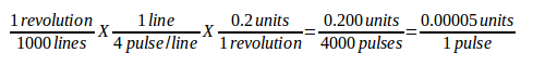
-
'BIAS = 0.000' - This is used by hm2-servo and some others. Bias is a constant amount that is added to the output. In most cases it should be left at zero. However, it can sometimes be useful to compensate for offsets in servo amplifiers, or to balance the weight of an object that moves vertically. bias is turned off when the PID loop is disabled, just like all other components of the output.
-
'P = 50' - The proportional gain for the axis servo. This value multiplies the error between commanded and actual position in machine units, resulting in a contribution to the computed voltage for the motor amplifier. The units on the P gain are volts per machine unit, e.g.,

-
'I = 0' - The integral gain for the axis servo. The value multiplies the cumulative error between commanded and actual position in machine units, resulting in a contribution to the computed voltage for the motor amplifier. The units on the I gain are volts per machine unit second, e.g.,

-
'D = 0' - The derivative gain for the axis servo. The value multiplies the difference between the current and previous errors, resulting in a contribution to the computed voltage for the motor amplifier. The units on the D gain are volts per machine unit per second, e.g.,
-
'FF0 = 0' - The 0th order feed forward gain. This number is multiplied by the commanded position, resulting in a contribution to the computed voltage for the motor amplifier. The units on the FF0 gain are volts per machine unit, e.g.,
-
'FF1 = 0' - The 1st order feed forward gain. This number is multiplied by the change in commanded position per second, resulting in a contribution to the computed voltage for the motor amplifier. The units on the FF1 gain are volts per machine unit per second, e.g.,
-
'FF2 = 0' - The 2nd order feed forward gain. This number is multiplied by the change in commanded position per second per second, resulting in a contribution to the computed voltage for the motor amplifier. The units on the FF2 gain are volts per machine unit per second per second, e.g.,

-
'OUTPUT_SCALE = 1.000' -
-
'OUTPUT_OFFSET = 0.000' - These two values are the scale and offset factors for the axis output to the motor amplifiers. The second value (offset) is subtracted from the computed output (in volts), and divided by the first value (scale factor), before being written to the D/A converters. The units on the scale value are in true volts per DAC output volts. The units on the offset value are in volts. These can be used to linearize a DAC. Specifically, when writing outputs, the Machinekit first converts the desired output in quasi-SI units to raw actuator values, e.g., volts for an amplifier DAC. This scaling looks like:
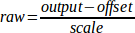
The value for scale can be obtained analytically by doing a unit analysis, i.e., units are [output SI units]/[actuator units]. For example, on a machine with a velocity mode amplifier such that 1 volt results in 250 mm/sec velocity.

Note that the units of the offset are in machine units, e.g., mm/sec, and they are pre-subtracted from the sensor readings. The value for this offset is obtained by finding the value of your output which yields 0.0 for the actuator output. If the DAC is linearized, this offset is normally 0.0.
The scale and offset can be used to linearize the DAC as well, resulting in values that reflect the combined effects of amplifier gain, DAC non-linearity, DAC units, etc.
To do this, follow this procedure.
-
Build a calibration table for the output, driving the DAC with a desired voltage and measuring the result.
-
Do a least-squares linear fit to get coefficients a, b such that
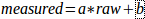
-
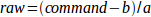
Note that we want raw output such that our measured result is identical to the commanded output. This means
-
-
As a result, the a and b coefficients from the linear fit can be used as the scale and offset for the controller directly.

See the following table for an example of voltage measurements.
| Raw | Measured |
|---|---|
-10 |
-9.93 |
-9 |
-8.83 |
0 |
-0.03 |
1 |
0.96 |
9 |
9.87 |
10 |
10.87 |
-
'MAX_OUTPUT = 10' - The maximum value for the output of the PID compensation that is written to the motor amplifier, in volts. The computed output value is clamped to this limit. The limit is applied before scaling to raw output units. The value is applied symmetrically to both the plus and the minus side.
-
'INPUT_SCALE = 20000' - in Sample configs
-
'ENCODER_SCALE = 20000' - in PNCconf built configs Specifies the number of pulses that corresponds to a move of one machine unit as set in the [TRAJ] section. For a linear axis one machine unit will be equal to the setting of LINEAR_UNITS. For an angular axis one unit is equal to the setting in ANGULAR_UNITS. A second number, if specified, is ignored. For example, on a 2000 counts per rev encoder, and 10 revs/inch gearing, and desired units of inch, we have:

Stepper
These parameters are relevant to axes controlled by steppers.
|
Warning
|
The following are custom INI file entries that you may find in a sample INI file or a wizard generated file. These are not used by the Machinekit software. They are only there to put all the settings in one place. For more information on custom INI file entries see the Custom Sections and Variables subsection. |
The following items might be used by a stepgen component.
-
'SCALE = 4000' - in Sample configs
-
'STEP_SCALE = 4000' - in PNCconf built configs Specifies the number of pulses that corresponds to a move of one machine unit as set in the [TRAJ] section. For stepper systems, this is the number of step pulses issued per machine unit. For a linear axis one machine unit will be equal to the setting of LINEAR_UNITS. For an angular axis one unit is equal to the setting in ANGULAR_UNITS. For servo systems, this is the number of feedback pulses per machine unit. A second number, if specified, is ignored.
For example, on a 1.8 degree stepper motor with half-stepping, and 10 revs/inch gearing, and desired machine units of inch, we have:

-
'ENCODER_SCALE = 20000' (Optionally used in PNCconf built configs) - Specifies the number of pulses that corresponds to a move of one machine unit as set in the [TRAJ] section. For a linear axis one machine unit will be equal to the setting of LINEAR_UNITS. For an angular axis one unit is equal to the setting in ANGULAR_UNITS. A second number, if specified, is ignored. For example, on a 2000 counts per rev encoder, and 10 revs/inch gearing, and desired units of inch, we have:
-
'STEPGEN_MAXACCEL = 21.0' - Acceleration limit for the step generator. This should be 1% to 10% larger than the axis MAX_ACCELERATION. This value improves the tuning of stepgen’s "position loop". If you have added backlash compensation to an axis then this should be 1.5 to 2 times greater than MAX_ACCELERATION.
-
'STEPGEN_MAXVEL = 1.4' - Older configuration files have a velocity limit for the step generator as well. If specified, it should also be 1% to 10% larger than the axis MAX_VELOCITY. Subsequent testing has shown that use of STEPGEN_MAXVEL does not improve the tuning of stepgen’s position loop.
[EMCIO] Section
-
'EMCIO = io' - Name of IO controller program
-
'CYCLE_TIME = 0.100' - The period, in seconds, at which EMCIO will run. Making it 0.0 or a negative number will tell EMCIO not to sleep at all. There is usually no need to change this number.
-
'TOOL_TABLE = tool.tbl' - The file which contains tool information, described in the User Manual.
-
'TOOL_CHANGE_POSITION = 0 0 2' - Specifies the XYZ location to move to when performing a tool change if three digits are used. Specifies the XYZABC location when 6 digits are used. Specifies the XYZABCUVW location when 9 digits are used. Tool Changes can be combined. For example if you combine the quill up with change position you can move the Z first then the X and Y.
-
'TOOL_CHANGE_WITH_SPINDLE_ON = 1' - The spindle will be left on during the tool change when the value is 1. Useful for lathes or machines where the material is in the spindle, not the tool.
-
'TOOL_CHANGE_QUILL_UP = 1' - The Z axis will be moved to machine zero prior to the tool change when the value is 1. This is the same as issuing a G0 G53 Z0.
-
'TOOL_CHANGE_AT_G30 = 1' - The machine is moved to reference point defined by parameters 5181-5186 for G30 if the value is 1. For more information on G30 and Parameters see the G Code Manual.
-
'RANDOM_TOOLCHANGER = 1' - This is for machines that cannot place the tool back into the pocket it came from. For example, machines that exchange the tool in the active pocket with the tool in the spindle.