
Basic HAL Tutorial
HAL Commands
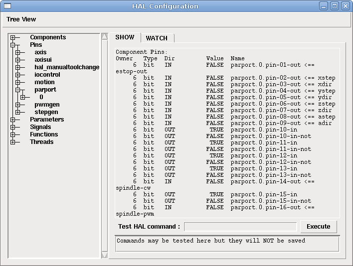
More detailed information can be found in the man page for halcmd 'man halcmd' in a terminal window. To see the HAL configuration and check the status of pins and parameters use the HAL Configuration window on the Machine menu in AXIS. To watch a pin status open the Watch tab and click on each pin you wish to watch and it will be added to the watch window.
Loading a component.
Nearly all components in Machinekit are now instantiable.
This is a major difference between Machinekit and Linuxcnc.
Instantiable means that a base component is created and multiple instances of that component can be loaded
at will at any time.
This completely does away with the shortcomings of fixed classic components, which must be loaded at startup
and thereafter no components can be loaded unless the session is halted and restarted.
There are 2 methods of loading instantiable components.
1. The classic loadrt method detailed below
2. By the newinst command below
Method 1. is retained for compatibility and will accept parameters of count= or names= to control numbers of instances created.
Method 2. gives the full range of instantiated component options, including direct renaming, setting the number of pin sets through pincount= and many others, if the component uses them.
loadrt
The command 'loadrt' loads a real time HAL component. Real time component functions need to be added to a thread to be updated at the rate of the thread. You cannot load a user space component into the real time space.
The syntax and an example:
loadrt <component> <options>

loadrt mux4 count=1
newinst
The command newinst, creates a new instance of a component. Components are added to threads just as with those loaded with loadrt.
newinst debounce db1 pincount=10The above command creates a new instance of debounce, called db1
It specifies db1 should have 10 sets of pins.
If a new name for debounce is not given, the default is debounce.0
(or a higher incremented number if a debounce.0 already exists)
newthread
newthread threadname [options] period
newthread servo fp 1000000Creates a new HAL thread named threadname which runs every period nanoseconds. Options are:
fp thread supports floating point
nofp (default) thread does not support floating point
cpu=N run thread on CPU #N
cgname=/N run thread in cgroup cpuset:N
NB. See threads and latency information for advanced settings.
nowait (experimental) ignores period, thread free-runs and must be synchronized externally
posix (experimental) non-realtime posix thread. Can make Linux system calls, but has no timing guarantees
addf
The command 'addf' adds a real time component function to a thread. You have to add a function from a HAL real time component to a thread to get the function to update at the rate of the thread.
If you used the Stepper Config Wizard to generate your config you will have two threads.
-
base-thread (the high-speed thread): this thread handles items that need a fast response, like making step pulses, and reading and writing the parallel port.
-
servo-thread (the slow-speed thread): this thread handles items that can tolerate a slower response, like the motion controller, ClassicLadder, and the motion command handler.
The syntax and an example:
addf <component> <thread>

addf mux4 servo-thread
loadusr
The command 'loadusr' loads a user space HAL component. User space programs are their own separate processes, which optionally talk to other HAL components via pins and parameters. You cannot load real time components into user space.
Flags may be one or more of the following:
| -W |
to wait for the component to become ready. The component is assumed to have the same name as the first argument of the command. |
| -Wn <name> |
to wait for the component, which will have the given <name>. This only applies if the component has a name option. |
| -w |
to wait for the program to exit |
| -i |
to ignore the program return value (with -w) |
| -n |
name a component when it is a valid option for that component. |
The syntax and examples:
loadusr <component> <options>

loadusr halui

loadusr -Wn spindle gs2_vfd -n spindle
In English it means loadusr wait for name spindle component gs2_vfd name spindle.
net
The command net creates a 'connection' between a signal and and one
or more pins. If the signal does not exist net creates the new signal.
This replaces the need to use the command newsig. The optional direction
indicators ⇐, ⇒ and <⇒ are not used by the net command.
We would encourage you not to use these at all, because instead of making this more readable, when wrongly used, they instead can give you a false sense of direction.
You can see the signal as the traces on a PCB, connecting an output
pin of a component with zero or more input pins. A signal is a variable, and the
inputs and outputs of components are pointers to this variable.
net signal-name <pin-name> <optional direction> (<pin-name>|<direction>)

net home-x axis.0.home-sw-in parport.0.pin-11-in
In the above example home-x is the signal name, axis.0.home-sw-in is a
Direction IN pin, ⇐ is the optional direction indicator, and
parport.0.pin-11-in is a Direction OUT pin. This may seem confusing but
the in and out labels for a parallel port pin indicates the physical way the
pin works not how it is handled in HAL.
One way to remember this: The Alphabet
n (net) comes before the s (signal and source) who come before the t (target) in the Alphabet. If you have trouble with the order of signal and source remember that i (signal) also comes before the o (source) in the Alphabet.
A second way to remember this:
(It sounds silly, but it really helps) is saying this line for 10 times :
|
Note
|
net signal source target1 target2 |
A pin can be connected to a signal if it obeys the following rules:
-
An IN pin can always be connected to a signal
-
An IO pin can be connected unless there’s an OUT pin on the signal
-
An OUT pin can be connected only if there are no other OUT or IO pins on the signal
The same <signal-name> can be used in multiple net commands to connect additional pins, as long as the rules above are obeyed.
![Signal Direction[[cap:Signal-Direction]]](/docs/hal/images/signal-direction.svg)
This example shows the signal xStep with the source being
stepgen.0.out and with two readers, parport.0.pin-02-out and
parport.0.pin-08-out. Basically the value of stepgen.0.out is written to
the signal xStep and that value is then read by parport.0.pin-02-out
and parport.0.pin-08-out.
#   signal    source            destination          destination
net xStep stepgen.0.out => parport.0.pin-02-out parport.0.pin-08-out
Since the signal xStep contains the value of stepgen.0.out (the
source) you can use the same signal again to send the value to another
reader. To do this just use the signal with the readers on another
line.
net xStep => parport.0.pin-02-outAn I/O pin like encoder.N.index-enable can be read or set as allowed by the component.
setp
The command 'setp' sets the value of a pin or parameter. The valid values will depend on the type of the pin or parameter. It is an error if the data types do not match.
Some components have parameters that need to be set before use. Parameters can be set before use or while running as needed. You cannot use setp on a pin that is connected to a signal.
The syntax and an example:
setp <pin/parameter-name> <value>

setp parport.0.pin-08-out TRUE
sets
The command 'sets' sets the value of a signal.
The syntax and an example:
sets <signal-name> <value>

net mysignal and2.0.in0 pyvcp.my-led

sets mysignal 1
It is an error if:
-
The signal-name does not exist
-
If the signal already has a writer
-
If value is not the correct type for the signal
unlinkp
The command 'unlinkp' unlinks a pin from the connected signal. If no signal was connected to the pin prior running the command, nothing happens. The 'unlinkp' command is useful for trouble shooting.
The syntax and an example:
unlinkp <pin-name>

unlinkp parport.0.pin-02-out
Obsolete Commands
The following commands are depreciated and may be removed from future versions. Any new configuration should use the 'net' command. These commands are included so older configurations will still work.
linksp
The command 'linksp' creates a 'connection' between a signal and one pin.
The syntax and an example:
linksp <signal-name> <pin-name>
linksp X-step parport.0.pin-02-out
The 'linksp' command has been superseded by the 'net' command.
linkps
The command 'linkps' creates a 'connection' between one pin and one signal. It is the same as linksp but the arguments are reversed.
The syntax and an example:
linkps <pin-name> <signal-name>

linkps parport.0.pin-02-out X-Step
The 'linkps' command has been superseded by the 'net' command.
newsig
the command 'newsig' creates a new HAL signal by the name <signame> and the data type of <type>. Type must be 'bit', 's32', 'u32' or 'float'. Error if <signame> all ready exists.
The syntax and an example:
newsig <signame> <type>

newsig Xstep bit
More information can be found in the HAL manual or the man pages for halrun.
HAL Data
Bit
A bit value is an on or off.
-
bit values = true or 1 and false or 0 (True, TRUE, true are all valid)
Float
A 'float' is a floating point number. In other words the decimal point can move as needed.
-
float values = a 64 bit floating point value, with approximately 53 bits of resolution and over 1000 bits of dynamic range.
For more information on floating point numbers see:
s32
An 's32' number is a whole number that can have a negative or positive value.
-
s32 values = integer numbers -2147483648 to 2147483647
u32
A 'u32' number is a whole number that is positive only.
-
u32 values = integer numbers 0 to 4294967295
HAL Files
If you used the Stepper Config Wizard to generate your config you will have up to three HAL files in your config directory.
-
my-mill.hal (if your config is named 'my-mill') This file is loaded first and should not be changed if you used the Stepper Config Wizard.
-
custom.hal This file is loaded next and before the GUI loads. This is where you put your custom HAL commands that you want loaded before the GUI is loaded.
-
custom_postgui.hal This file is loaded after the GUI loads. This is where you put your custom HAL commands that you want loaded after the GUI is loaded. Any HAL commands that use pyVCP widgets need to be placed here.
HAL Components
Two parameters are automatically added to each HAL component when it is created. These parameters allow you to scope the execution time of a component.
.time
.tmax
Time is the number of CPU cycles it took to execute the function.
Tmax is the maximum number of CPU cycles it took to execute the function. Tmax is a read/write parameter so the user can set it to 0 to get rid of the first time initialization on the function’s execution time.
Logic Components
HAL contains several real time logic components. Logic components follow a 'Truth Table' that states what the output is for any given input. Typically these are bit manipulators and follow electrical logic gate truth tables.
and2
The 'and2' component is a two input 'and' gate. The truth table below shows the output based on each combination of input.
Syntax
and2 [count=N] | [names=name1[,name2...]]Functions
and2.n
Pins
and2.N.in0 (bit, in)
and2.N.in1 (bit, in)
and2.N.out (bit, out)
Truth Table
| in0 | in1 | out |
|---|---|---|
False |
False |
False |
True |
False |
False |
False |
True |
False |
True |
True |
True |
not
The 'not' component is a bit inverter.
Syntax
not [count=n] | [names=name1[,name2...]]Functions
not.all
not.n
Pins
not.n.in (bit, in)
not.n.out (bit, out)
Truth Table
| in | out |
|---|---|
True |
False |
False |
True |
or2
The 'or2' component is a two input OR gate.
Syntax
or2[count=n] | [names=name1[,name2...]]Functions
or2.n
Pins
or2.n.in0 (bit, in)
or2.n.in1 (bit, in)
or2.n.out (bit, out)
Truth Table
| in0 | in1 | out |
|---|---|---|
True |
False |
True |
True |
True |
True |
False |
True |
True |
False |
False |
False |
xor2
The 'xor2' component is a two input XOR (exclusive OR)gate.
Syntax
xor2[count=n] | [names=name1[,name2...]]Functions
xor2.n
Pins
xor2.n.in0 (bit, in)
xor2.n.in1 (bit, in)
xor2.n.out (bit, out)
Truth Table
| in0 | in1 | out |
|---|---|---|
True |
False |
True |
True |
True |
False |
False |
True |
True |
False |
False |
False |
Logic Examples
An 'and2' example connecting two inputs to one output.
loadrt and2 count=1

addf and2.0 servo-thread

net my-sigin1 and2.0.in0 <= parport.0.pin-11-in

net my-sigin2 and2.0.in1 <= parport.0.pin-12-in

net both-on parport.0.pin-14-out <= and2.0.out
In the above example one copy of and2 is loaded into real time space and added to the servo thread. Next pin 11 of the parallel port is connected to the in0 bit of the and gate. Next pin 12 is connected to the in1 bit of the and gate. Last we connect the and2 out bit to the parallel port pin 14. So following the truth table for and2 if pin 11 and pin 12 are on then the output pin 14 will be on.
Conversion Components
weighted_sum
The weighted_sum converts a group of bits to an integer. The conversion is the sum of the 'weights' of the bits that are on plus any offset. The weight of the m-th bit is 2^m. This is similar to a binary coded decimal but with more options. The 'hold' bit stops processing the input changes so the 'sum' will not change.
The following syntax is used to load the weighted_sum component.
loadrt weighted_sum wsum_sizes=size[,size,...]Creates weighted sum groups each with the given number of input bits (size).
To update the weighted_sum you need to attach process_wsums to a thread.
addf process_wsums servo-threadThis updates the weighted_sum component.
In the following example clipped from the HAL Configuration window in Axis the bits '0' and '2' are true and there is no offset. The 'weight' of 0 is 1 and the 'weight' of 2 is 4 so the sum is 5.
Component Pins:
Owner   Type  Dir         Value  Name
    10  bit   In           TRUE  wsum.0.bit.0.in
    10  s32   I/O             1  wsum.0.bit.0.weight
    10  bit   In          FALSE  wsum.0.bit.1.in
    10  s32   I/O             2  wsum.0.bit.1.weight
    10  bit   In           TRUE  wsum.0.bit.2.in
    10  s32   I/O             4  wsum.0.bit.2.weight
    10  bit   In          FALSE  wsum.0.bit.3.in
    10  s32   I/O             8  wsum.0.bit.3.weight
    10  bit   In          FALSE  wsum.0.hold
    10  s32   I/O             0  wsum.0.offset
    10  s32   Out             5  wsum.0.sum