Image to G Code
- What is a depth map?
- Integrating image-to-gcode with the AXIS user interface
- Using image-to-gcode
- Option Reference
- Units
- Invert Image
- Normalize Image
- Expand Image Border
- Tolerance (units)
- Pixel Size (units)
- Plunge Feed Rate (units per minute)
- Feed Rate (units per minute)
- Spindle Speed (RPM)
- Scan Pattern
- Scan Direction
- Depth (units)
- Step Over (pixels)
- Tool Diameter
- Safety Height
- Tool Type
- Lace bounding
- Contact angle
- Roughing offset and depth per pass
What is a depth map?
A depth map is a greyscale image where the brightness of each pixel corresponds to the depth (or height) of the object at each point.
Integrating image-to-gcode with the AXIS user interface
Add the following lines to the '[FILTER]' section of your .ini file to make AXIS automatically invoke image-to-gcode when you open a .png, .gif, or .jpg image
PROGRAM_EXTENSION = .png,.gif,.jpg Grayscale Depth Image
png = image-to-gcode
gif = image-to-gcode
jpg = image-to-gcode
The standard 'sim/axis.ini' configuration file is already configured this way.
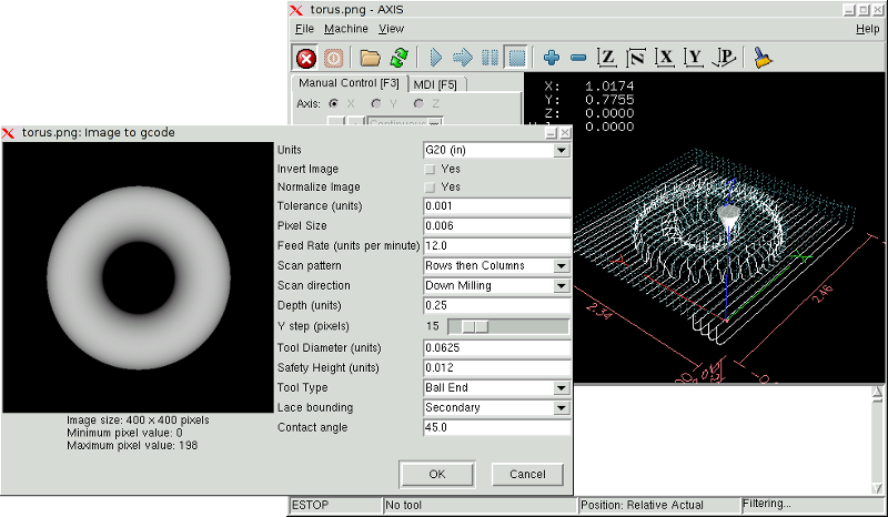
Using image-to-gcode
Start image-to-gcode either by opening an image file in AXIS, or by invoking image-to-gcode from the terminal, as follows:
image-to-gcode torus.png > torus.ngcVerify all the settings in the right-hand column, then press OK to create the gcode. Depending on the image size and options chosen, this may take from a few seconds to a few minutes. If you are loading the image in AXIS, the gcode will automatically be loaded and previewed once image-to-gcode completes. In AXIS, hitting reload will show the image-to-gcode option screen again, allowing you to tweak them.
Option Reference
Units
Specifies whether to use G20 (inches) or G21 (mm) in the generated g-code and as the units for each option labeled '(units)'.
Invert Image
If “no”, the black pixel is the lowest point and the white pixel is the highest point. If “yes”, the black pixel is the highest point and the white pixel is the lowest point.
Normalize Image
If 'yes', the darkest pixel is remapped to black, the lightest pixel is remapped to white.
Expand Image Border
If 'None', the input image is used as-is, and details which are at the very edges of the image may be cut off. If 'White' or 'Black', then a border of pixels equal to the tool diameter is added on all sides, and details which are at the very edges of the images will not be cut off.
Tolerance (units)
When a series of points are within 'tolerance' of being a straight line, they are output as a straight line. Increasing tolerance can lead to better contouring performance in Machinekit, but can also remove or blur small details in the image.
Pixel Size (units)
One pixel in the input image will be this many units—usually this number is much smaller than 1.0. For instance, to mill a 2.5x2.5-inch object from a 400x400 image file, use a pixel size of .00625, because 2.5 / 400 = .00625.
Plunge Feed Rate (units per minute)
The feed rate for the initial plunge movement.
Feed Rate (units per minute)
The feed rate for other parts of the path.
Spindle Speed (RPM)
The spindle speed S code that should be put into the gcode file.
Scan Pattern
Possible scan patterns are:
-
Rows
-
Columns
-
Rows, then Columns
-
Columns, then Rows
Scan Direction
Possible scan directions are:
-
Positive: Start milling at a low X or Y axis value, and move towards a high X or Y axis value
-
Negative: Start milling at a high X or Y axis value, and move towards a low X or Y axis value
-
Alternating: Start on the same end of the X or Y axis travel that the last move ended on. This reduces the amount of traverse movements
-
Up Milling: Start milling at low points, moving towards high points
-
Down Milling: Start milling at high points, moving towards low points
Depth (units)
The top of material is always at 'Z=0'. The deepest cut into the material is 'Z=-depth.'
Step Over (pixels)
The distance between adjacent rows or columns. To find the number of pixels for a given units distance, compute 'distance/pixel size' and round to the nearest whole number. For example, if 'pixel size=.006' and the desired step over 'distance=.015', then use a Step Over of 2 or 3 pixels, because '.015/.006=2.5''.'
Tool Diameter
The diameter of the cutting part of the tool.
Safety Height
The height to move to for traverse movements. image-to-gcode always assumes the top of material is at 'Z=0'.
Tool Type
The shape of the cutting part of the tool. Possible tool shapes are:
-
Ball End
-
Flat End
-
45 degree “vee”
-
60 degree “vee”
Lace bounding
This controls whether areas that are relatively flat along a row or column are skipped. This option only makes sense when both rows and columns are being milled. Possible bounding options are:
-
None: Rows and columns are both fully milled.
-
Secondary: When milling in the second direction, areas that do not strongly slope in that direction are skipped.
-
Full: When milling in the first direction, areas that strongly slope in the second direction are skipped. When milling in the second direction, areas that do not strongly slope in that direction are skipped.
Contact angle
When 'Lace bounding' is not 'None', slopes greater than 'Contact angle' are considered to be 'strong' slopes, and slopes less than that angle are considered to be weak slopes.
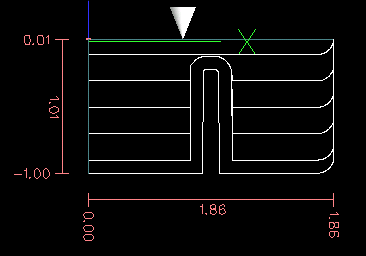
Roughing offset and depth per pass
Image-to-gcode can optionally perform rouging passes. The depth of successive roughing passes is given by 'Roughing depth per pass'. For instance, entering 0.2 will perform the first roughing pass with a depth of 0.2, the second roughing pass with a depth of 0.4, and so on until the full Depth of the image is reached. No part of any roughing pass will cut closer than Roughing Offset to the final part. The following figure shows a tall vertical feature being milled. In this image, Roughing depth per pass is 0.2 inches and roughing offset is 0.1 inches.