
Pico Drivers
Pico Systems has a family of boards for doing analog servo, stepper, and PWM (digital) servo control. The boards connect to the PC through a parallel port working in EPP mode. Although most users connect one board to a parallel port, in theory any mix of up to 8 or 16 boards can be used on a single parport. One driver serves all types of boards. The final mix of I/O depends on the connected board(s). The driver doesn’t distinguish between boards, it simply numbers I/O channels (encoders, etc) starting from 0 on the first board. The driver is named hal_ppmc.ko The analog servo interface is also called the PPMC for Parallel Port Motion Control. There is also the Universal Stepper Controller, abbreviated the USC. And the Universal PWM Controller, or UPC.
Installing:
loadrt hal_ppmc port_addr=<addr1>[,<addr2>[,<addr3>...]]The 'port_addr' parameter tells the driver what parallel port(s) to check. By default, '<addr1>' is 0x0378, and '<addr2>' and following are not used. The driver searches the entire address space of the enhanced parallel port(s) at 'port_addr', looking for any board(s) in the PPMC family. It then exports HAL pins for whatever it finds. During loading (or attempted loading) the driver prints some useful debugging messages to the kernel log, which can be viewed with 'dmesg'.
Up to 3 parport busses may be used, and each bus may have up to 8 (or possibly 16 PPMC) devices on it.
Command Line Options
There are several options that can be specified on the loadrt command line. First, the USC and UPC can have an 8-bit DAC added for spindle speed control and similar functions. This can be specified with the extradac='0xnn[,0xmm]' parameter. The part enclosed in [ ] allows you to specify this option on more than one board of the system. The first hex digit tells which EPP bus is being referred to, it corresponds to the order of the port addresses in the port_addr parameter, where <addr1> would be zero here. So, for the first EPP bus, the first USC or UPC board would be described as '0x00', the second USC or UPC on the same bus would be '0x02'. (Note that each USC or UPC takes up two addresses, so if one is at 00, the next would have to be 02.)
Alternatively, the 8 digital output pins can be used as additional digital outputs, it works the same way as above with the syntax : extradout=0xnn'. The extradac and extradout options are mutually exclusive on each board, you can only specify one.
The UPC and PPMC encoder boards can timestamp the arrival of encoder counts to refine the derivation of axis velocity. This derived velocity can be fed to the PID hal component to produce smoother D term response. The syntax is : timestamp='0xnn[,0xmm]', this works the same way as above to select which board is being configured. Default is to not enable the timestamp option. If you put this option on the command line, it enables the option. The first 'n' selects the EPP bus, the second one matches the address of the board having the option enabled. The driver checks the revision level of the board to make sure it has firmware supporting the feature, and produces an error message if the board does not support it.
The PPMC encoder board has an option to select the encoder digital filter frequeency. (The UPC has the same ability via DIP switches on the board.) Since the PPMC encoder board doesn’t have these extra DIP switches, it needs to be selected via a command-line option. By default, the filter runs at 1 MHz, allowing encoders to be counted up to about 900 KHz (depending on noise and quadrature accuracy of the encoder.) The options are 1, 2.5, 5 and 10 MHz. These are set with a parameter of 1,2,5 and 10 (decimal) which is specified as the hex digit "A". These are specified in a manner similar to the above options, but with the frequency setting to the left of the bus/address digits. So, to set 5 MHz on the encoder board at address 3 on the first EPP bus, you would write : enc_clock='0x503'
Pins
In the following pins, parameters, and functions, <port> is the parallel port ID. According to the naming conventions the first port should always have an ID of zero. All the boards have some method of setting the address on the EPP bus. USC and UPC have simple provisions for only two addresses, but jumper foil cuts allow up to 4 boards to be addressed. The PPMC boards have 16 possible addresses. In all cases, the driver enumerates the boards by type and exports the appropriate HAL pins. For instance, the encoders will be enumerated from zero up, in the same order as the address switches on the board specify. So, the first board will have encoders 0 — 3, the second board would have encoders 4 — 7. The first column after the bullet tells which boards will have this HAL pin or parameter associated with it. All means that this pin is available on all three board types. Option means that this pin will only be exported when that option is enabled by an optional parameter in the loadrt HAL command. These options require the board to have a sufficient revision level to support the feature.
-
'(All s32 output) ppmc.<port>.encoder.<channel>.count' - Encoder position, in counts.
-
'(All s32 output) ppmc.<port>.encoder.<channel>.delta' - Change in counts since last read, in raw encoder count units.
-
'(All float output) 'ppmc.<port>.encoder.<channel>.velocity' - Velocity scaled in user units per second. On PPMC and USC this is derived from raw encoder counts per servo period, and hence is affected by encoder granularity. On UPC boards with the 8/21/09 and later firmware, velocity estimation by timestamping encoder counts can be used to improve the smoothness of this velocity output. This can be fed to the PID HAL component to produce a more stable servo response. This function has to be enabled in the HAL command line that starts the PPMC driver, with the timestamp=0x00 option.
-
'(All float output) ppmc.<port>.encoder.<channel>.position' - Encoder position, in user units.
-
'(All bit bidir) ppmc.<port>.encoder.<channel>.index-enable' - Connect to axis.#.index-enable for home-to-index. This is a bidirectional HAL signal. Setting it to true causes the encoder hardware to reset the count to zero on the next encoder index pulse. The driver will detect this and set the signal back to false.
-
'(PPMC float output) ppmc.<port>.DAC.<channel>.value' - sends a signed value to the 16-bit Digital to Analog Converter on the PPMC DAC16 board commanding the analog output voltage of that DAC channel.
-
'(UPC bit input) ppmc.<port>.pwm.<channel>.enable' - Enables a PWM generator.
-
'(UPC float input) ppmc.<port>.pwm.<channel>.value' - Value which determines the duty cycle of the PWM waveforms. The value is divided by 'pwm.<channel>.scale', and if the result is 0.6 the duty cycle will be 60%, and so on. Negative values result in the duty cycle being based on the absolute value, and the direction pin is set to indicate negative.
-
'(USC bit input) ppmc.<port>.stepgen.<channel>.enable' - Enables a step pulse generator.
-
'(USC float input) ppmc.<port>.stepgen.<channel>.velocity' - Value which determines the step frequency. The value is multiplied by 'stepgen.<channel>.scale' , and the result is the frequency in steps per second. Negative values result in the frequency being based on the absolute value, and the direction pin is set to indicate negative.
-
'(All bit output) ppmc.<port>.din.<channel>.in' - State of digital input pin, see canonical digital input.
-
'(All bit output) ppmc.<port>.din.<channel>.in-not' - Inverted state of digital input pin, see canonical digital input.
-
'(All bit input) ppmc.<port>.dout.<channel>.out' - Value to be written to digital output, see canonical digital output.
-
'(Option float input) ppmc.<port>.DAC8-<channel>.value' - Value to be written to analog output, range from 0 to 255. This sends 8 output bits to J8, which should have a Spindle DAC board connected to it. 0 corresponds to zero Volts, 255 corresponds to 10 Volts. The polarity of the output can be set for always minus, always plus, or can be controlled by the state of SSR1 (plus when on) and SSR2 (minus when on). You must specify extradac = 0x00 on the HAL command line that loads the PPMC driver to enable this function on the first USC ur UPC board.
-
'(Option bit input) ppmc.<port>.dout.<channel>.out' - Value to be written to one of the 8 extra digital output pins on J8. You must specify extradout = 0x00 on the HAL command line that loads the ppmc driver to enable this function on the first USC or UPC board. extradac and extradout are mutually exclusive features as they use the same signal lines for different purposes. These output pins will be enumerated after the standard digital outputs of the board.
Parameters
-
'(All float) ppmc.<port>.encoder.<channel>.scale' - The number of counts / user unit (to convert from counts to units).
-
'(UPC float) ppmc.<port>.pwm.<channel-range>.freq' - The PWM carrier frequency, in Hz. Applies to a group of four consecutive PWM generators, as indicated by '<channel-range>'. Minimum is 610Hz, maximum is 500KHz.
-
'(PPMC float) ppmc.<port>.DAC.<channel>.scale' - Sets scale of DAC16 output channel such that an output value equal to the 1/scale value will produce an output of + or - value Volts. So, if the scale parameter is 0.1 and you send a value of 0.5, the output will be 5.0 Volts.
-
'(UPC float) ppmc.<port>.pwm.<channel>.scale' - Scaling for PWM generator. If 'scale' is X, then the duty cycle will be 100% when the 'value' pin is X (or -X).
-
'(UPC float) ppmc.<port>.pwm.<channel>.max-dc' - Maximum duty cycle, from 0.0 to 1.0.
-
'(UPC float) ppmc.<port>.pwm.<channel>.min-dc' - Minimum duty cycle, from 0.0 to 1.0.
-
'(UPC float) ppmc.<port>.pwm.<channel>.duty-cycle' - Actual duty cycle (used mostly for troubleshooting.)
-
'(UPC bit) ppmc.<port>.pwm.<channel>.bootstrap' - If true, the PWM generator will generate a short sequence of pulses of both polarities when E-stop goes false, to reset the shutdown latches on some PWM servo drives.
-
'(USC u32) ppmc.<port>.stepgen.<channel-range>.setup-time' - Sets minimum time between direction change and step pulse, in units of 100ns. Applies to a group of four consecutive step generators, as indicated by '<channel-range>'. Values between 200 ns and 25.5 us can be specified.
-
'(USC u32) ppmc.<port>.stepgen.<channel-range>.pulse-width' - Sets width of step pulses, in units of 100ns. Applies to a group of four consecutive step generators, as indicated by '<channel-range>'. Values between 200 ns and 25.5 us may be specified.
-
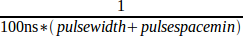
'(USC u32) ppmc.<port>.stepgen.<channel-range>.pulse-space-min' - Sets minimum time between pulses, in units of 100ns. Applies to a group of four consecutive step generators, as indicated by '<channel-range>'. Values between 200 ns and 25.5 us can be specified. The maximum step rate is:
-
'(USC float) ppmc.<port>.stepgen.<channel>.scale' - Scaling for step pulse generator. The step frequency in Hz is the absolute value of 'velocity' * 'scale'.
-
'(USC float) ppmc.<port>.stepgen.<channel>.max-vel' - The maximum value for 'velocity'. Commands greater than 'max-vel' will be clamped. Also applies to negative values. (The absolute value is clamped.)
-
'(USC float) ppmc.<port>.stepgen.<channel>.frequency' - Actual step pulse frequency in Hz (used mostly for troubleshooting.)
-
'(Option float) ppmc.<port>.DAC8.<channel>.scale' - Sets scale of extra DAC output such that an output value equal to scale gives a magnitude of 10.0 V output. (The sign of the output is set by jumpers and/or other digital outputs.)
-
'(Option bit) ppmc.<port>.dout.<channel>.invert' - Inverts a digital output, see canonical digital output.
-
'(Option bit) ppmc.<port>.dout.<channel>.invert' - Inverts a digital output pin of J8, see canonical digital output.
Functions
-
'(All funct) ppmc.<port>.read' - Reads all inputs (digital inputs and encoder counters) on one port. These reads are organized into blocks of contiguous registers to be read in a block to minimize CPU overhead.
-
'(All funct) ppmc.<port>.write' - Writes all outputs (digital outputs, stepgens, PWMs) on one port. These writes are organized into blocks of contiguous registers to be written in a block to minimize CPU overhead.